
 Europe


Connect to the Long Term Success with the Right DC Cables for PV Plants
28/10/2022The deployment of renewables has been growing at a rapid pace in recent years, reaching record levels, according to IRENA. Among all renewable technologies, solar photovoltaic (PV) power has been dominating the renewables industry for many years.
As PV plant owners channel their efforts towards strengthening the performance and efficiency of PV plant operations, DC cabling selection cannot be overlooked. Based on the interpretation of relevant IEC standards and considering factors such as safety, bifacial gains, cable carrying capacity, cable loss and voltage drop, plant owners can now accurately determine appropriate cabling to ensure safe and stable operation across the PV system’s life cycle.
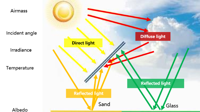
The actual PV module performance in the field is greatly affected by local environmental conditions. The short circuit current given in a PV module datasheet is based on a typical standard testing conditions (i.e. STC: irradiance=1000W/m2, spectrum Air Mass=1.5, cell temperature= 25°C), thus it does not take into consideration of the rear surface current in the case of bifacial modules. Factors such as cloud enhancement, temperatures, irradiance spikes, and over-irradiance on the rear surface due to albedo can significantly impact the actual short circuit current for PV modules.
Choosing the Right DC Cables Is Critical for Both PV Plant’s Performance and Safety
PV plant owners need to make informed decisions about the selection of equipment across the whole PV system to ensure high-performance levels. For example, DC cables are the lifelines of PV systems, as they interconnect modules to combiner boxes and inverters.
Plant owners need to ensure that the size of the DC cable installed is carefully and correctly chosen for the current and voltage of the PV system. The cables used for wiring the DC section of a grid-connected PV system also need to withstand the extremes of the environmental, voltage, and current conditions in which they operate. This includes the heating effects of both the current and solar gain, especially if installed close to the PV modules.
Here are some crucial areas of considerations for installing the correct DC cabling for solar PV systems.
How to Decide on the Right DC Cabling Design and Installation
In PV system design, short-term cost considerations can result in poor equipment selection and lead to safety and performance issues in the long run, including catastrophic consequences such as fires. The following areas need to be carefully assessed to meet respective national safety and quality standards:
- Voltage drop limit: Losses in solar PV cabling must be limited, both DC losses in the strings of solar panels and AC losses at the output of inverters. A way to limit these losses is to minimize the voltage drop in cables. In general, a DC voltage drop of less than 1% is desirable and must not exceed 2%. A high DC voltage drop also increases voltage dispersion of the PV strings connected to the same Maximum Power Point Tracking (MPPT), resulting in higher mismatch losses.
- Cable loss: To ensure the energy yield of the PV plant, it is recommended that the cable loss of the entire LV cable (from the modules to the transformer) should not exceed 2% or 1.5%.
- Current carrying capacity: Derating factors should be taken into consideration, such as the way of laying cables, temperature rise, laying distance, and number of parallel cables, which reduce the current carrying capacity of the cables.
IEC Standards for Cable Selection of Bifacial PV Modules
Standards are essential for ensuring the reliability, safety, and quality of PV systems, including cabling. Globally there are several recognized standards for the use of DC cables. One of the most comprehensive standards are the IEC standards.
IEC 62548 sets out design requirements for PV arrays, including DC array wiring, electrical protection devices, switching, earthing provisions. The latest draft of the IEC 62548 specifies the current calculation method for bifacial modules. IEC 61215:2021 outlines the definition and test requirements of bifacial PV modules. It introduces the solar irradiance test conditions of bifacial module.
Accounting for an Overcurrent Protection Device
An overcurrent protection device is a piece of equipment used to protect against the potentially dangerous effects of overloads, short-circuits, or ground faults. The most common overcurrent protection devices are circuit breakers and fuses.
The overcurrent protection device will cut off the circuit when the reverse current exceeds the current protection value, so the forward and reverse currents flowing through the DC cable will never be higher than the rated current of the device. In this case, the DC cable should have a carrying capacity equal to the rated current of the overcurrent protection device.
Iz>=In
Where Iz is the current carrying capacity of cable under field condition, In is the current rating of the overcurrent protection device.
Over current protection nominal rating In=1,1 ´ NSA´ ISTRING MAX
Where NSA is the number of strings in parallel, ISTRING MAX is the max current of the PV strings: ISTRING MAX = 1,25 * KCorr x ISC MOD,Where Kcorr is a location and design correction factor,for bifacial module it is usually 1.1(however can be determined by other methods described in the IEC62548), ISC MOD is the module short circuit current.
If there is no overcurrent protection device in the circuit, plant owners need to consider the maximum forward current and maximum reverse current that may flow through the DC cable respectively, and then take the larger value of the two in the selecting the right cable.
Accounting for Cable Installation Conditions
When designing and installing DC cabling, it's essential to calculate the current carrying capacity of the cable under certain field conditions to ensure the cable is not overloaded. An empirical formula can be used to determine the current carrying capacity of the cable after derating (Iz):
The formula includes various factors affecting the nominal current carrying capacity (I0) including different soil temperatures (f1), multiple cables laid in parallel directly in the soil (f2), soil thermal resistance (f3), and buried depths (f4).
A Real Life Example from the Middle East
Here is a case where a large ground PV power station in the Middle East uses the process outlined here to analyze and determine DC cable selection for both safety and performance. The PV array configuration comprises:
- Bifacial PV modules, generating power of 540 W with maximum power usage.
- A rated voltage of 41.3 V, a maximum power point current of 13.13 A, a short circuit current of 13.89 A, and the bifaciality of the PV module is 70%.
- 28 PV modules in series in a PV string.
- The photovoltaic support adopts horizontal single-axis tracking system, and the height above the ground is 1.5 m.
- DC combiner box with 16-in and 1-out is adopted.
- The whole PV array has 30 DC combiner boxes are integrated into centralized inverters.
- Kcorr is 1.1, which is simulated by PVsyst software.
- Desired Cable current carrying capacity Iz=In=1,1 ´ NSA´ ISTRING MAX=1.1*16*1.25*1.1*13.89=336.14A
- Total derating factor Ktot= 0.93´0.75´0.8´1=0.558
- Cable nominal current carrying capacity I0=Iz/Ktot=336.14/0.558=602.4A
Based on the PV array configuration, the nominal current carrying capacity of the DC cable used in this case should be greater than 602.4 A. The nominal current carrying capacity of the cable is selected based on the manufacturer's datasheet. (Or according to the cable selection standard of IEC60364-5-52, but the corresponding derating coefficient must also be selected according to the standard.)
The formula resulted in a recommendation of two parallels 2×300 mm2 aluminum DC cabling from the PV string combiner box to the inverter. The cable length was also reviewed to ensure that the voltage drop of the DC cable and total cable losses met project specified requirements. To ensure that the DC voltage drop is less than 2%, the specifications of some long-distance cables should be increased from 2 x 300 mm2 to 2 x 400 mm2. At the same time, it should be noted that the cable laying coefficient will be further reduced when two cables are laid in parallel.
We can see that due to the radiation, temperature rise, gain at the back of the bifacial modules, and the derating coefficient of cables, DC cables with a thicker diameter will be applied, which increases the cost. With the purpose of controlling costs and ensuring plant safety, the DC cable length should be shortened or the DC current should be limited by power electronics equipment, such as string inverters.
The Importance of PV Equipment Selection and Inverter Configuration
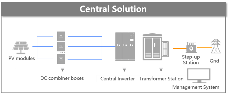
In the configuration of central inverter, multiple PV strings are connected in parallel into a DC combiner box, and multiple combiner boxes are connected in parallel into the inverter.
Therefore, the maximum output current at the combiner box and the input current at the inverter are constantly varying and of significant uncertainty. There are safety risks and additional design margins that must be considered during electrical equipment selection (fuses, disconnectors, cables in PV subarray and PV array), which significantly increases the final balance of system cost.
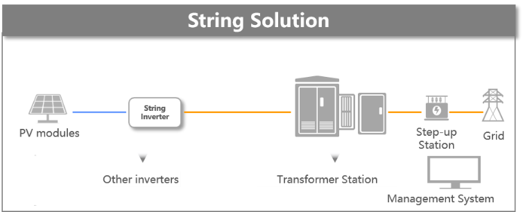
In contrast, string inverter solution convert the fluctuating, uncertain energy on the PV side into controllable electricity output. The inverter limits the current output thus the diameter of the inverter output cable does not need to consider the changes in the light, temperature, and bifacial modules. This allows designers to select the most cost-effective cables and overcurrent protection devices for their projects. Moreover, string inverter has a shorter DC cable and lower DC voltage drop, which result in less mismatch loss and more electricity generation inherently.
In conclusion, unlike conventional energy, the operating current of the photovoltaic module is greatly affected by environmental conditions and bifacial gain. These factors needs to be fully considered in cable selection during the design phase, along with proper restrictions on voltage drop and cable losses, to ensure the long term ROI of PV plants.
Solar-Powered 5G Livestream from Amboseli Drives Interest in Kenyan Tourism Boosting Economic Recovery Efforts
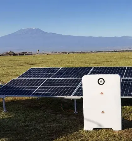
On World Environment Day, Sunday June 5, Safaricom, Huawei, and China Media Group (CMG) partnered with the Ministry of Tourism to organize a solar-powered livestream from Amboseli National Park that was broadcast globally online and on TV. The livestream used a 5G network whose extremely fast speeds enabled a high quality viewing experience and is just one way that technology is playing a key role in supporting the growth of tourism. Reaching up to 100 million impressions, the event informed viewers of the importance of the natural environment and wildlife, as well as increasing interest in Kenyan tourism in support of the Magical Kenya Campaign. This is particularly important in light of the economic recovery post COVID-19 when the tourism industry was hit particularly badly.
Read more >
Huawei Presents FusionSolar All-Scenario Smart PV & Storage Solution at Intersolar 2021
[Munich, 6 October 2021] At Intersolar 2021 Europe, Huawei presents the new-generation FusionSolar All-scenario Smart PV & Storage Solution, It covers “4+1” scenarios: Large-scale Utility Scenario, Green Residential Power 2.0, Green C&I Power 1.0, and Off-grid (fuel removal) Power Supply Solutions and Energy Cloud, aiming to accelerate the shift to low-carbon generation and bridge the energy divide.
Read more >
Huawei Smart PV Community is Back Online!
After a long summer break, the highly anticipated Huawei Smart PV Community is now back, and it is bigger and better! For those who haven’t joined us, Huawei Smart PV Community is a free sharing platform targeting our users and installers.
Read more >
